Glass type and main properties
Glass materials play a pivotal role in numerous aspects of human life, owing to their distinctive characteristics such as transparency, durability, and adaptability. Their applications span a broad spectrum, encompassing macro-sized items like containers, windows, and displays, as well as micro-sized components such as micro-lenses, micro-sensors, and micro-fluidic devices. The versatility of glass is evident in its usage across various domains.
In response to specific requirements, diverse glass materials have been engineered. Examples include pure SiO2 quartz and fused silica, as well as SiO2 infused with metal elements like Na, K, Al, etc. Table 1a/b provides a comprehensive overview of the fundamental thermal and optical properties of four commonly employed types of glass materials.
Examining these properties reveals that the glass materials exhibit fragility due to their exceptionally low thermal expansion behavior.
Simultaneously, their transparency across the UV to IR wavelength range results from the absence of absorption, making them ideal for a wide array of applications.
| Table 1A: Typical Thermal Properties | |||
| Glass Type | Ingredients | Melting Points | Thermal Expansion Coefficient |
| Fused Silica | SiO2 | 1710ºC | 0.5 x 10⁻⁶/ºC |
| Aluminosilicate Glass | Al2O3-MgO-B2O3-SiO2 | 1600-1800oC | 9.8 x 10⁻⁶/ºC |
| Borosilicate Glass | 4R₂O-3B₂O₃-9SiO | 1470oC | 3.3 x 10⁻⁶/ºC |
| Soda-Lime Glass | Na₂O-CaO-6SiO₂ | 1500-1600oC | 8 x 10⁻⁶/ºC |
| Table 1B: Typical Optical Properties | |
| Glass Type | Optical Absorption Coefficient |
| Fused Silica |
~<0.001cm-1@700nm-1.06um ~<0.001cm-1@400nm-700nm ~<0.001cm-1@200nm-300nm |
| Aluminosilicate Glass (AS87) |
~<0.1cm-1@700nm-1.06um ~<0.1cm-1@400nm-700nm ~0.1-5.0cm-1@200nm-300nm |
| Borosilicate Glass |
~<0.001cm-1@700nm-1.06um ~<0.001cm-1@400nm-700nm ~<0.001cm-1@200nm-300nm |
| Soda-Lime Glass |
~<0.01cm-1@700nm-1.06um ~0.01-0.1cm-1@400nm-700nm ~0.1-0.2cm-1@200nm-300nm |
Laser Glass Micro-processing Technology
The utilization of laser technology in glass material processing has evolved over the past few decades, emerging as an essential technique for achieving precise and intricate tasks such as cutting, drilling, marking, and surface patterning. This application is particularly significant for relatively thin glass in the range of tens of micrometers to tens of micrometers. In contrast to traditional mechanical processing methods, laser processing has garnered increasing popularity across various industries, driven by several distinct advantages. These advantages are highlighted in Table 2, underscoring the superior capabilities of laser processing compared to conventional methods.
Within the realm of laser glass processing, this article specifically focuses on the technique of laser cutting glass using a variety of laser sources.
| Table 2: Advantages of Laser Processing Glass | |
| 1. Precision and Accuracy | Allowing for intricate and detailed cuts for creating complex designs. |
| 2. Versatility | Allowing for direct customization of shapes and patterns. |
| 3. Reduced Material Waste | Resulting a smaller kerf (width of cut). |
| 4. Non-Contact Process | Reducing risk of damage to the glass and eliminating needs for physical tooling. |
| 5. High Speed and Efficiency | Suitable for mass production and large-scale manufacturing, leading to high productivity. |
| 6. Minimal Heat Affected Zone (HAZ) | Helping prevent distortion, micro-fractures, or changes in material properties. |
| 7. Complex Geometries | Allowing for the creation of intricate and complex geometries. |
By showcasing practical examples, readers can gain valuable insights into AOC’s expertise and technological capabilities in the field of glass cutting.
Targeting the unique challenges posed by the brittle and highly transparent properties of glass materials, a trio of laser 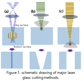 glass cutting methods has emerged, each employing distinct mechanisms of laser interaction. These methods are categorized based on their approach to: (a) internal material modification (dicing), (b) ablation from the top surface (top-down ablation), and (c) ablation from the bottom surface (bottom-up ablation), as illustrated in Figure 1.
In Table 3, technical details are presented to offer a comparative analysis of the pros and cons associated with each method, facilitating a comprehensive understanding of their operational intricacies and practical implications. For example, method-(a) utilizes a shaped laser beam (Bessel beam) to precisely damage the glass structure along the direction of the beam’s propagation. This method ensures minimal to no material loss from the base material during the process, which also known as laser stealthy dicing. Method-(b) involves the use of a focused laser beam to ablate material, starting from the top surface and progressing towards the bottom surface.
This technique, known as top-down ablation, efficiently removes material layer by layer.
In contrast, Method-(c) employs a focused laser beam to ablate material, starting from the bottom surface and progressing towards the top surface. This approach, known as bottom-up ablation, provides an alternative method for precise material removal offering distinct advantages in certain applications. After a decade of dedicated effort, each method has successfully refined its process, leveraging precisely.
| Table 3: Comparison of Three Laser Glass Cutting Methods | |||
| Method | Pros | Cons | Laser |
| (a) Stealthy Dicing |
|
|
|
| (b) Top-down Ablation |
|
|
|
| (c) Bottom-up Ablation |
|
|
|
Laser Glass Cutting Examples
In this section, we will highlight our significant accomplishments in processing diverse features in glass using the methods introduced earlier, leveraging suitable laser sources.
Case-1: glass cutting using method-(a: dicing).
In this process, a focused ps-1064nm laser Bessel beam with an extended depth of focus of up to 20mm is utilized. The depth of focus directly correlates with the thickness of the glass to be cut. Moreover, achieving efficient cutting necessitates higher laser power and burst pulse mode to enhance the modification process. As previously mentioned, a secondary process is required to split the glass using CO2 laser heating due to the significant difference in thermal expansion between the original glass and the modified glass. Figure 2 illustrates the AOC’s industry glass laser stealthy dicing system, which employs either ps-1064nm or ps-532nm laser, depending on the application. However, unless there is a specific requirement, such as high reflection coating at 1064nm on the glass surface, the ps-1064nm laser is typically preferred due to its higher power output.
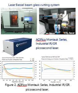
AOC has engineered a series of dicing modules tailored for precision cutting across varying thicknesses of glass. Each module is designed for a distinct depth of focus, enabling users to select the most suitable one according to the thickness of the glass being processed.
In Figure 3, optical microscope images depict the fine cutting of a 0.6mm thick mobile phone cover glass. Notably, the images reveal exceptionally sharp edges with chipping sizes <2um, and an absence of tapering, highlighting the module’s ability to achieve high-edge quality.
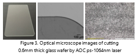
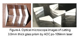
Figure 4 shows optical images of a 3.0mm thick prism, exemplifying flawless cutting that ensures superior device quality for micro-optics device applications. These images underscore the precision and reliability of AOC’s cutting technology, essential for demanding optical applications.
Case-2: glass cutting using method-(b: top-down ablation).
In this process, a laser beam is precisely focused on the material’s top surface, removing material layer by layer in a method known as normal laser ablation. For glass, which must absorb the laser light, this can occur through linear-absorption, defect-absorption, or nonlinear absorption mechanisms. Thus, for high-quality cutting, the ideal laser sources are either ns-UV laser (355nm) or Ultrafast laser (ps /fs laser).
Figure 5 illustrates AOC’s standard high-precision laser ablation-based micro-processing system, capable of utilizing ns-lasers, ps-la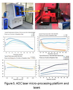 sers, and fs-lasers, based on specific processing needs.
Table 4 summarizes AOC’s study comparing glass cutting using ns-355nm, ps-1064nm/532nm, and fs-1030nm/515nm lasers.
| Table 4: Comparison of Glass Cutting with NS, PS, and FS Laser | ||
| Laser | Laser Fluence | Chipping Size |
| ns-355nm laser | ~100-150J/cm2 | ~40-60 um |
| ps-1064nm/532nm laser | ~50-100J/cm2 | <10 um |
| fs-1030nm/515nm laser | ~10-50J/cm2 | <1um |
The lower linear absorption of glass at a 355nm wavelength can lead to unsatisfactory laser cutting quality. Therefore, ps or fs lasers are recommended for this type of top-down ablation-based glass cutting, utilizing multiphoton (nonlinear) absorption to achieve precise and controlled material removal.
In the provided examples, Figure 6 illustrates an optical microscope image of the cutting edge of Aluminosilicate glass using ns-355nm laser top-down direct ablation. The measured chipping size is approximately 45.7µm.
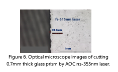
Figure 7a/b illustrates an optical microscope image of the cutting edge of Aluminosilicate glass using ps-1064nm and fs-515nm laser, respectively. The measured chipping size is <5um with ps-1064nm laser and invisible with fs-515nm laser, respectively.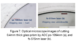
Thus, the top-down laser ablation technique excels in precision cutting of thin glass (<0.5mm), particularly when employing picosecond (ps) or femtosecond (fs) lasers, ensuring superior quality results.
Case-3: glass cutting using method- (c: bottom-up ablation).
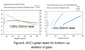
In contrast to top-down ablation, this process involves the transmission of a laser beam through the glass workpiece, focusing on the bottom surface. Material removal begins at the bottom surface, progresses upward, and ends at the top surface. Two conditions must be met for this process to be successful. First, the laser must not be absorbed by the glass. Second, as indicated in Table 3, the ideal lasers for this type of process are either short ns-532nm, extremely short ns-532nm, or ps-532nm lasers. Figure 8 illustrates the laser specifications of AOC’s ns-532nm and sub-ns-532nm lasers, respectively.
Unlike traditional direct linear and nonlinear absorption in top-down ablation, bottom-up ablation involves indirect absorption. This process is driven by the plasma induced by the previous pulse, le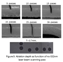 ading to material removal.
Figure 9 demonstrates the sequential process of bottom-up ablation using a ns-532nm laser, showcasing the change in ablation depth with each laser beam scanning pass. Notably, the ablated trench maintains a consistent kerf width from start to finish, resulting in a cutting cross-section with a frosted surface texture, free from observable cracking and chipping.
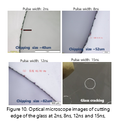
In our observations, we have noted a significant correlation between the laser pulse width and the quality of cutting in this process. When the laser pulse width exceeds 12ns, we have observed that cracking of the glass begins at the cutting edge. This phenomenon is likely due to an increase in the thermal effect within the material.
Figure 10 illustrates the optical microscope images of the cutting edges of 0.6mm thick aluminosilicate glass using 532nm laser at pulse with of 2ns, 8ns, 12ns, and 15ns, respectively.
 All evidence indicates that for cutting glass using the bottom-up pulsed 532nm laser ablation method, a shorter pulse width results in smaller chipping sizes. Therefore, for this process, a <12ns-532nm laser is recommended, particularly for processing small, close-loop features in thicker glass (>0.5mm) as shown in figure 11.
Summary: After a decade of collective efforts, AOC has developed a comprehensive laser cutting solution for glass tailored to specific applications.